 The
LP-1 FM Translator PreamplifierThe
LP-1 FM Translator Preamplifier
The
LP-1 FM Translator PreamplifierThe
LP-1 FM Translator Preamplifier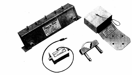
DESCRIPTION:
The LP-1 FM translator preamplifier has been specifically
designed to select a weak FM signal in the presence of strong interfering
signals.
One of the more serious problems with FM translators
is the loss of sensitivity due to strong RF signals other than the desired
signal (referred to as "desense"). This is often caused by the translator's
own output getting through the input RF section and finding its way to
the first mixer. The result is an increased noise level which can degrade
the desired signal especially if it's weak. In a worst case of only 400
kHz separation between input and output, a 1000 to 1 (30dB) improvement
can be expected by using the LP-1.
Another problem which often exists is caused by
the presence of very strong undesired signals located close enough to the
translator site to completely flood the front end of the translator. A
preamplifier that can handle large signal levels without overloading along
with a good filter is what's needed. The LP-1 fulfills this need.
All of the above is accomplished by means of a high
level preamplifier using a single VMOS transistor, followed by a very selective
five section helical resonator filter. Because the preamplifier will accept
large input signals without overloading, no intermodulation products are
generated. The boosted signal at the preamplifier output contains both
the desired signal and the undesired ones. This composite signal is then
passed through the filter (FL100) which strongly
attenuates the undesired signals. The result is a dramatic improvement
in translator performance.
SPECIFICATIONS:
| Frequency: | All FM channels (filter is tuned to a specific channel) |
| Overall Gain: | 15dB Minimum, 20 dB typical (depends on desired filter bandwidth) |
| Noise Figure: | 4dB Maximum |
| Intermodulation: | None appreciable under the following conditions:
2uV desired signal 10,000uV undesired signal with 400kHz separation |
| 1dB Compression
(typical) |
A typical amplifier with 20dB gain will have the gain compressed by 1dB with an input of -6dBm and an output of +13dBm (measured with a single tone input) |
| Rejection: | 400kHz removed: 17dB
600kHz removed: 35dB 800kHz removed: 47dB 1MHz removed: 60dB |
| Impedance | 50 Ohm or 75 Ohm |
| Connectors | UHF standard, others available |
| Power Requirements | +27 to +35 VDC, 150mA. This voltage is imposed on the receive coax through the voltage adapter. This makes it possible to use voltage from the translator power supply. RF connectors impedance normally match that of the preamplifier and filter but other combinations are available. The standard DC connector is a banana plug. |
| Mechanical | The preamplifier is mounted in a weather proof box intended for tower mounting. It will mount to 3/4" through 2 1/2" diameter pipe or angle, as well as any appropriate flat surface. The filter has provisions for mounting on a flat surface near the translator. The voltage adapter simply mounts in the transmission line between the filter and the preamplifier but nearest the filter. Construction is all aluminum except for the mounting hardware. Rack mount for filter is available. |
