| Frequency | Any frequency from 88 to 108 MHz |
| RF Output Impedance | 50 or 75 ohms |
| Sensitivity (For 30db of quieting)
(For 50db of quieting) |
2uV across 50 ohms
10 uV across 50 ohms |
| Noise Figure | 4db |
| Automatic Gain Control Range | 120dB |
| Bandwidth | 240KHz |
| Image Rejection | 100dB |
| RF Input Impedance
UHF connector standard (other connectors available) |
50 or 75 ohms |
| Frequency | Any frequency from 88 to 108 MHz |
| Type of Emission | 180F3 |
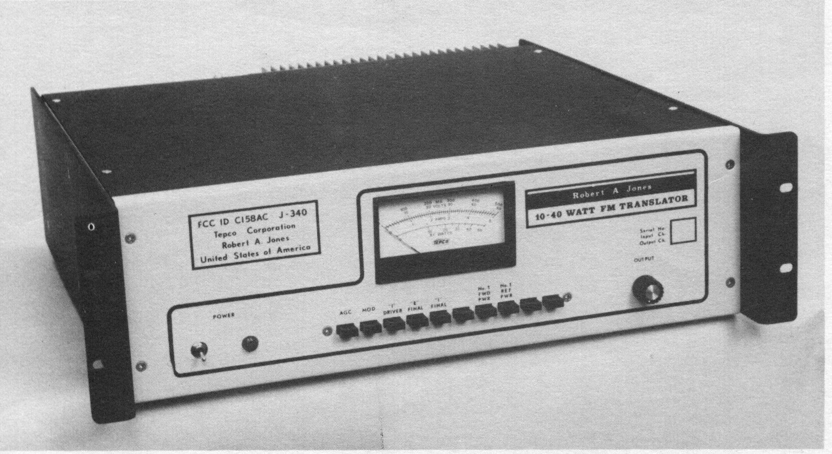
| Rated Output Power | 10 to 40 watts |
| Power Output Regulation | Within 1% for any change In signal Input level or AC line variation of 10% |
| RF Output Impedance. UHF connector standard (other connectors available) | 50 or 75 Ohms |
| Harmonics | -80db or better |
| Spurious Output (600 kHz removed) | -80db or better |
| FM Signal To Noise Ratio | -70db or better |
| AM Noise (Referred to carrier) Ratio | -65db or better |
| Overall Frequency Stability | +/-1800 Hz from -30 to +50 deg C |
| Intermediate Frequency | 10.7 MHz |
| Power Requirements: For 40 Watts RF | AC: lOOVA or DC: 2.8 Amps at 28 Volts |
| Optional Audio Modulator | As per 74.123 |
| Dimensions | 19" by 13" x 3 1/2" |
| Weight | 25 lbs (Approx. 30 lbs. shipping) |